Design Introduction
When excavation heights exceed 5 ft (1.5 m), we need to design a lateral support system. This is often a cantilever soldier pile or embedded retaining wall. A cantilever wall of this kind is permissible up to about 17 ft (5.2 m).
Backfill Earth Pressure
We can determine the backfill earth pressure using Rankine, Coulomb, Boussinesq, Muller-Breslau or Terzaghi & Peck method. Often, we need the soil’s friction angle and the soil unit weight. If pile-soil friction is to be ignored, then we can use Rankine Method. If pile-soil friction is taken as Phi/2, but the pile is vertical (not slanted), then Coulomb or Boussinesq method can be used for determining the backfill earth pressure. If you have a slanted pile, then we refer to Muller-Breslau equations. If you prefer a more general approach, the Terzaghi & Peck 5 soil classification method may be utilized.
Passive Earth Resistance
It is important to note the slope at the toe or at the dredge line. If it is descending, the passive resistance is much lower than if the toe is level. If soil’s friction angle is greater than 30 Degrees, it is best to limit the pile-soil friction angle to Phi/3, specially when using Coulomb method. In addition, we should factor the computed Ultimate Kp by 1.25 to 1.50 if we use wall friction. If Rankine method is used, it is already conservative & not necessary to use a Factor of Safety on Ultimate Kp.
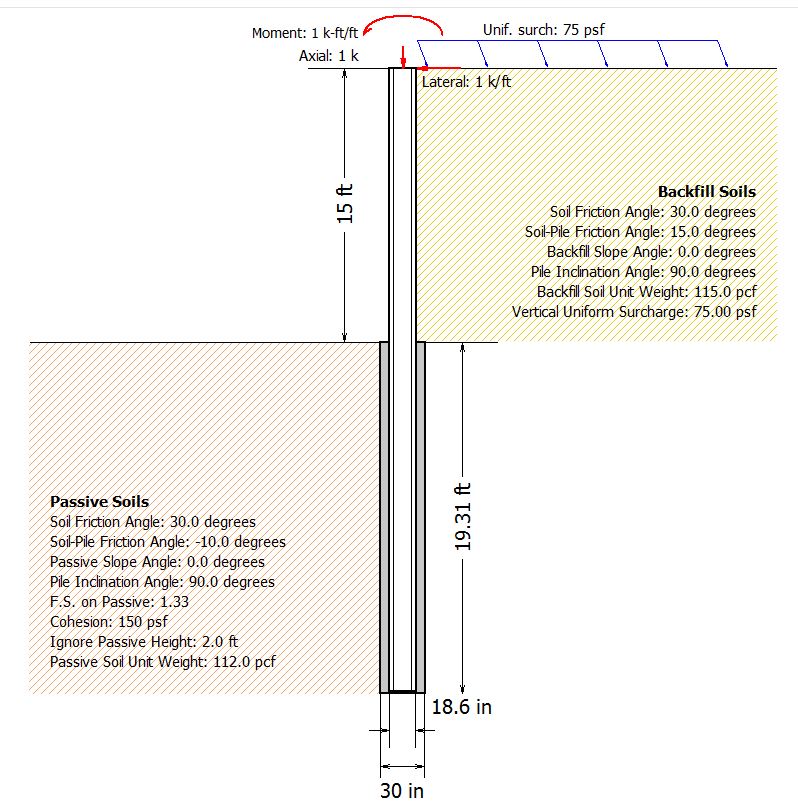
Loading Diagram
This is often provided in the Geotechnical Engineering Report. For Cantilever Piles, it should be simple. It should give the Backfill Pressure per ft or meter depth and the Passive Resistance per ft or m depth, with a maximum passive resistance. For example, 45 pcf Backfill Pressure and 300 pcf Passive Resistance & a maximum of 3,000 pcf. This is a typical loading diagram:
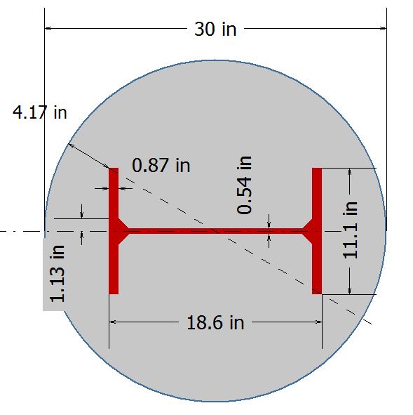
Structural Beam Reinforcement
Once you have the loading diagram generated, you can pick an I-Beam and check first if it fits the drilled pier. As a minimum, we should provide a 2 inch (50 mm) diagonal clearance. See below:
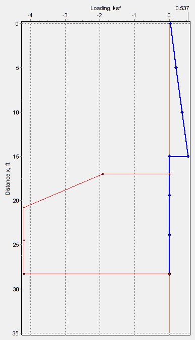
Then you should plot Shear, Moment, Slope and Deflection with Depth. Also a check should be made on P-M interaction if we have axial loads. In addition a check should be made on Slenderness Ratio, kL/r and to stay within allowable lateral deflection @ the top of the Pile.
SoilStructure Software CANTILEVER SHORING performs all of the above checks. The program has SI units, English Units, AISC Beams, Australian Beams, European Beams & British Beams.