1. We just want to use the skin friction values in the soils report- how do I enter that in the software?
Drilled Pier software (DP) asks you for “Ultimate” skin friction and then divides it by 2.0 factor of safety or the value of FS you enter to arrive at “Allowable” skin friction value most often shown on your soils report. Therefore enter two times the “allowable” value and set F.S. Skin Friction = 2 to match your soils report.
2. It is asking for many geotechnical inputs for the drilled shaft foundation design but I am a structural engineer- what do you suggest?
Drilled pier software gives you a range of suitable values for (a) lateral subgrade modulus & (b) ultimate skin friction. Just pick the soil type & consistency as shown on your soils report (like stiff Clay or medium dense Sand) and aim for the middle range of the displayed lateral SG modulus and Ult. skin friction values.
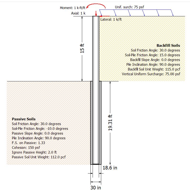
3. Passive wedge-can that be used for passive bearing?
Yes, that value is equal to 0.08*Phi and is multiplied to the isolated pier when determining lateral capacity. For example, if friction angle is 30 Degrees, Passive Wedge multiplier is 0.08*30 or 2.4.
4. Uplift Load, is that load along the pier surface from soil swelling?
Yes you can get uplift due to swelling or expansive soils on a drilled shaft foundation. You can also get uplift or tension from structural loads such as wind or seismic effects. The program will display geotechnical & structural tension capacities.
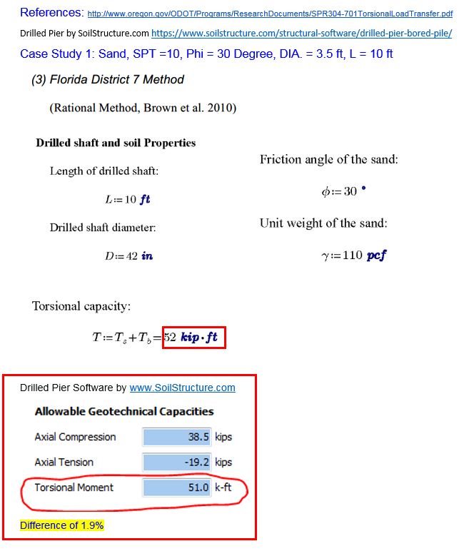
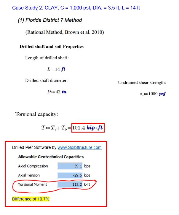
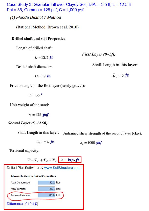
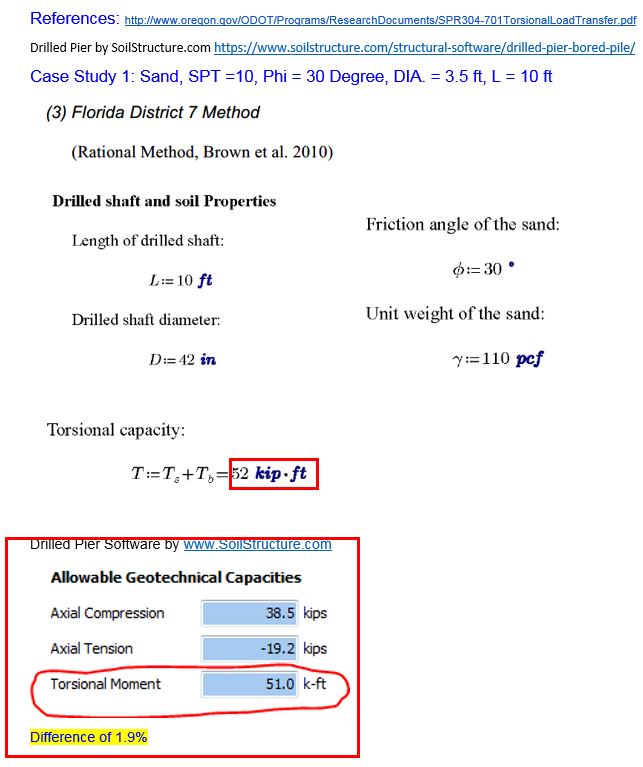
6. F.S. Torsional Moment is not a value given to us in the soil report.
Torsional moment can occur when you have a cantilever sign foundation or when the shear load applied to the drilled shaft foundation is off center. Based on calibration of DP software with instrumented drilled pier results, we recommend F.S. against Torsional moment in the range of 3.3 to 3.5.
7. What if the pier extends up several feet above the grade, can this situation be modeled in your software?
Yes. In such a case, your lateral load (shear) remains the same and your bending moment becomes shear load*stick up height. Then choose your “Free Head” or “Fixed Head” boundary condition.
8. Can Drilled Pier software help me with depth to rebar cage?
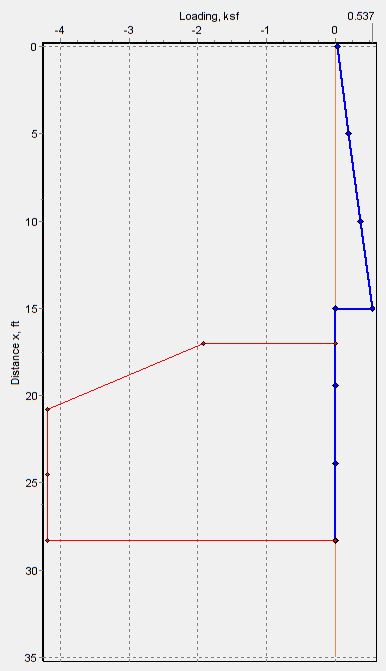
Yes. On the results pages, you will see bending moment versus depth. For L/D (pier length/pier diameter) of 10 or less, we suggest rebar cage to be full length since you have a short rigid pier. However, for L/D >10, you may terminate rebar cage at 1 m or 3 ft below the depth where moment is equal to zero.
9. Where do I enter my load combinations for a drilled shaft design?
Under “Reinforcement” tab, you can override Pu, Mu, Vu and Tu (Axial, Bending Moment, Shear and Torsional Moment) values using the applicable load combination. DP software automatically factor mx. service level shear moment by 1.6 each, and axial downward load by 1.2.
10. Can the drilled pier software help me with bay mud?
Yes. When you are in compressible soils, the pier tends to settle faster then the surrounding soil. This causes negative skin friction which results in additional downward load which does not affect the allowable pier capacity. DP software computes the magnitude of this downdrag force.
11. How about vertical pier capacity & settlement calculations?
In some parts of the world only end bearing pressure is used, other regions only skin friction values are adopted while yet some other parts both end bearing & skin friction are utilized. Regardless of regional preferences, the initial load on a caisson or bored pile, causes elastic shortening of the pier. As you increase this downward load, skin friction picks up the load and yet as you increase the load, end bearing & tip resistance becomes engaged. Drilled Pier software will tell the capacity of a drilled shaft due to short term (Total Stress Analysis), long term capacity (effective Stress Analysis) and also the 3 components of vertical drilled pier settlement. These three components are settlement due to elastic pier shortening, settlement due to skin friction mobilization & settlement due to end bearing resistance.
12. I like your program- I can design several piers in a short time.
Thank you. We agree. The program performs axial, lateral & reinforcement design of a drilled shaft foundation under a single hood. Very few structures have just Axial only load or Lateral only load.
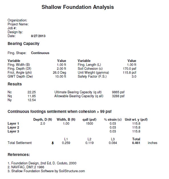
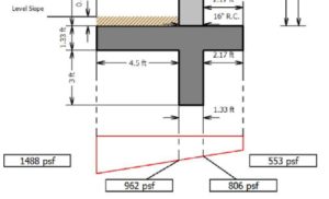 Bearing Press.(EFP method)
 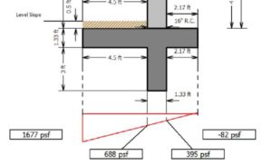 Bearing Press.(Phi/C /Gamma method)
